Utilizziamo i cookie per rendere migliore la tua esperienza di navigazione. Per rispettare la nuova direttiva sulla privacy, è necessario chiedere il tuo consenso per impostare i cookie. Per saperne di più.


The SEGGER Linker makes linking faster, optimizes application size, and solves common linking problems that usually arise in embedded development.
The SEGGER Linker is a fast and flexible linker for Arm- and RISC-V-based embedded systems. Designed to be very flexible but simple to use, it is written from scratch without legacy code or legacy thinking, targeting the requirements of embedded developers.
The linker does not only offer easier configuration of memory layout and symbol placement, it can also drastically decrease code size and even improve the execution speed of the linked application.
Support for Popular Architectures
The SEGGER Linker can link applications for various targets. The Arm variant supports Cortex-M devices (ARMv6-M, ARMv7-M, ARMv7E-M, ARMv8-M Baseline, ARMv8-M Mainline) as well as 32-bit Cortex-A devices (ARMv7-A). The RISC-V variant supports all 32-bit RISC-V devices (RV32E, RV32EMA, RV32EMAC, RV32I, RV32IMA, RV32IMAC, RV32IMAF, RV32IMAFC, RV32G, RV32GC).
Optimize the Application
The SEGGER Linker does not blindly link all input together. It includes features and optimization for producing smaller, faster applications compared to other linkers.
Linker optimizations work on all compilation units, not just input from C source files. They also work on third-party object-code libraries. Most features of the SEGGER Linker apply to all variants depending on the target architecture. Every application can benefit from them.
- Modular Linkage links in only what is required, discarding unused code and data.
- Flexible Placement efficiently arranges code and data in memory, leaving no gaps and producing small binaries. It also reduces call distances and improves locality.
- Dynamic Runtime Initialization automatically includes only the initialization code for included sections.
- Initialization Data Compression reduces readonly memory used to initialize readwrite sections at runtime.
- Function Deduplication eliminates duplicate functions that have identical bodies at the instruction level.
- Code Deduplication eliminates duplicate readonly data sections.
- String Merging even eliminates string constants which match the end of another one.
Optimizations for RISC-V
RISC-V ELF objects enable further optimizations that the SEGGER Linker can use. These optimizations can drastically reduce code size, countering some limitations of the RISC-V instruction set.
- Tail Optimization produces a single tail instruction sequence for two (or more) functions that can share that single sequence, reducing code size.
- Automatic Inlining can completely inline small functions to reduce code size or improve execution speed.
- Outlining can reduce code size by finding sequences of instructions that are common between functions, even finding them within a function and moving them into a subroutine, replacing each extraction with a call to the subroutine.
- Smart Function Relocation and Relaxation uses well-tuned heuristics to lay out code, reducing function call sizes.
- Smart Data Relocation and Relaxation finds the best layout for data.
- Springboarding can further reduce code size by transforming groups of calls and jumps through common springboards.
| Architecture | Library | Linker | R/O Code | R/O Data | Total R/O |
|---|---|---|---|---|---|
| RV32IMAC | GNU | GNU | 43176 | 4608 | 47784 |
| RV32IMAC | GNU | SEGGER | 37772 | 3623 | 41395 |
| RV32IMAC | GNU | SEGGER + outlining | 36086 | 3623 | 39709 |
Setting Up the Target’s Memories
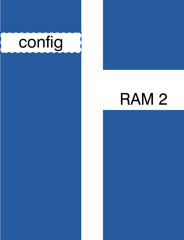 Small embedded systems – usually microcontrollers with built-in memories – are complex. Typically, they have separate memory area for flash and RAM and might also use external memories.
RAM is usually also divided into distinct regions to enhance performance, so they can be accessed simultaneously by the CPU and peripherals.
Flash memory can contain "keep-out" areas, e.g. calibration data or bootloader APIs that may not be overwritten by application code. Certain values might also have to be set at fixed address, such as flash protection bytes or fixed-address jump tables.
The SEGGER Linker has been designed to work with these complex memory layouts.
System configuration is done with a SEGGER Linker Script. Its simple yet powerful syntax enables flexible and tailored memory layout and section placement with just a few lines of statements.
Integrate the Linker into the Build System
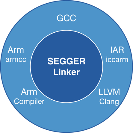 The SEGGER Linker has mainly been designed to replace the GNU Linker, used with GCC toolchains. While the GNU Linker is great for host applications, the SEGGER Linker has a lot of advantages for use in embedded development.
The SEGGER Linker accepts ELF object files generated by standard-conforming toolchains, such as GCC, Clang, and others.
Alongside the SEGGER Compiler and Runtime Library, the SEGGER Linker is readily included in SEGGER Embedded Studio. It can also be used with any other build system, such as make or Cmake to be integrated in existing environments.
The SEGGER Linker provides fast linkage speed, even for complex or large applications. It can speed up linking up to 5 times, effectively reducing development time.
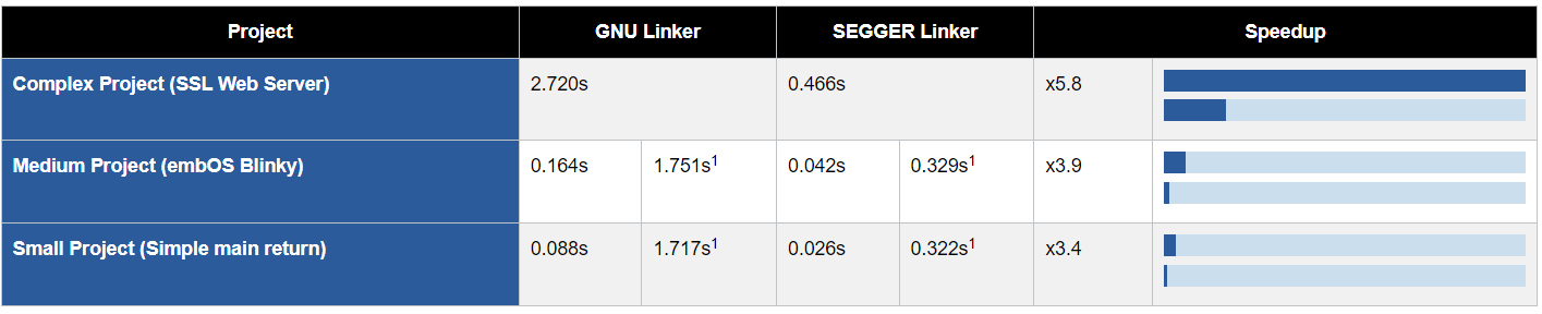
1: Linked with all object files from the complex project, which are discarded in other projects.
Analyze the Linked Application
In addition to the ELF output, the SEGGER Linker can generate a comprehensive map file of the linked application. SEGGER Linker map files are readable and understandable. For better overview and navigation map files can also be generated in HTML format.
Map files come in handy, when you need to know more about how your application is linked. SEGGER Linker generated map files allow for easy analysis of the executable image and provide answers to following questions:
- How much ROM And RAM does my application need?
- How much code and data is pulled in because of one or multiple particular symbols?
- How much space does a module need?
- Where are my symbols placed?
- Is my symbol where I want it to be?
- Where are gaps of unused memory in the image?
Control Placement with Linker Scripts
Linker scripts for the SEGGER Linker are easy to write and provide full flexibility and smart features.
SEGGER Linker Scripts for most embedded systems can be written with about 20 to 50 lines of statements.
All which has to be done is:
- Define the memory regions.
- Define blocks to group input sections.
- Configure initialization.
- Place inputs in the memory regions.
Detailed information on how to write linker scripts can be found at wiki.segger.com/SEGGER_Linker_Script_Files
Defining Memory Regions
Memory regions define which address ranges of the target systems to use. In the simple and most common case, there is just one Flash and one RAM region. The SEGGER Linker also enables more detailed configuration and partitioning.
A flash range can be split into multiple regions to separate bootlaoder and application. Multiple ranges, such as two separate SRAMS, can be combined to one region to enable easy placement in the whole memory. Regions can even contain holes, which might be required for keep-out areas or configuration data to be retained.
Defining Blocks
Blocks can be used to keep certain sections and symbols together. While the SEGGER Linker arranges all inputs for efficient memory use, some sections should be treated like one input. These can be grouped in a block.
Blocks can also be used to reserve space that is used by the application without placing actual symbols into it. This for example enables definition of areas for stack and heap of a given size and ensures there is enough space for those left.
Configuring Initialization
With dynamic runtime initialization, the SEGGER Linker takes care of how to initialize readwrite sections. This is commonly done by copying an initialization image from flash to RAM. Configuring the initialization enables compression of initialization images to save flash space, as well as using user functions to be called for initialization if the associated sections contain any data.
Placing Inputs
SEGGER Linker Scripts can fully control which symbols, sections, or blocks go into which memory. They can also enable to let the linker do what it is best at and let it place everything automatically for most efficient use.
The most common case is simple and elegant: Interrupt vectors need to be at the beginning of flash, readonly data and code may be placed anywhere in flash,
read-write data is placed anywhere in RAM, and at the end of the RAM some space is reserved for stack and heap. This can be achieved with just 4 placement statements.
Linker Script Example
This is an example of a linker script, which can define a complete application.
// Define Memory Regions
  define memory with size = 4G;
  define region FLASH = [from 0x00000000 size 512k];
  define region RAM   = [from 0x1fff0000 size 64k] + [0x20000000 size 192k];
  // Define Blocks
  define block heap  with size = 10240,  alignment = 8, readwrite access { };
  define block stack with size = 2048, alignment = 8, readwrite access { };
  // Configure Initialization
  do not initialize                       { section .non_init, section .non_init.*};
  initialize by copy with packing=auto    { section .data, section .data.* };
  initialize by symbol __SEGGER_init_heap { block heap  };
  // Place Inputs
  place at start of FLASH                 { section .vectors };
  place in FLASH                          { readexec, readonly };
  place in RAM                            { readwrite, zeroinit };
  place at end of RAM                     { block heap, block stack };
Control Placement with Linker Scripts
Linker scripts for the SEGGER Linker are easy to write and provide full flexibility and smart features.
SEGGER Linker Scripts for most embedded systems can be written with about 20 to 50 lines of statements.
All which has to be done is:
- Define the memory regions.
- Define blocks to group input sections.
- Configure initialization.
- Place inputs in the memory regions.
Detailed information on how to write linker scripts can be found at wiki.segger.com/SEGGER_Linker_Script_Files
Linker Script Example
This is an example of a linker script, which can define a complete application.
//  Define Memory Regions
  define memory with size = 4G;
  define region FLASH = [from 0x00000000 size 512k];
  define region RAM   = [from 0x1fff0000 size 64k] + [0x20000000 size 192k];
  // Define Blocks
  define block heap  with size = 10240,  alignment = 8, readwrite access { };
  define block stack with size = 2048, alignment = 8, readwrite access { };
  // Configure Initialization
  do not initialize                       { section .non_init, section .non_init.*};
  initialize by copy with packing=auto    { section .data, section .data.* };
  initialize by symbol __SEGGER_init_heap { block heap  };
  // Place Inputs
  place at start of FLASH                 { section .vectors };
  place in FLASH                          { readexec, readonly };
  place in RAM                            { readwrite, zeroinit };
  place at end of RAM                     { block heap, block stack };
Defining Memory Regions
Memory regions define which address ranges of the target systems to use. In the simple and most common case, there is just one Flash and one RAM region. The SEGGER Linker also enables more detailed configuration and partitioning.
A flash range can be split into multiple regions to separate bootloader and application. Multiple ranges, such as two separate SRAMS, can be combined to one region to enable easy placement in the whole memory. Regions can even contain holes, which might be required for keep-out areas or configuration data to be retained.
Defining Blocks
Blocks can be used to keep certain sections and symbols together. While the SEGGER Linker arranges all inputs for efficient memory use, some sections should be treated like one input. These can be grouped in a block.
Blocks can also be used to reserve space that is used by the application without placing actual symbols into it. This for example enables definition of areas for stack and heap of a given size and ensures there is enough space for those left.
Configuring Initialization
With dynamic runtime initialization, the SEGGER Linker takes care of how to initialize readwrite sections. This is commonly done by copying an initialization image from flash to RAM.
Configuring the initialization enables compression of initialization images to save flash space, as well as using user functions to be called for initialization if the associated sections contain any data.
Placing Inputs
SEGGER Linker Scripts can fully control which symbols, sections, or blocks go into which memory. They can also enable to let the linker do what it is best at and let it place everything automatically for most efficient use.
The most common case is simple and elegant: Interrupt vectors need to be at the beginning of flash, readonly data and code may be placed anywhere in flash,
read-write data is placed anywhere in RAM, and at the end of the RAM some space is reserved for stack and heap. This can be achieved with just 4 placement statements.
Tecnologix offre supporto gestito direttamente dal Team di sviluppo.
Non esitare a metterti in contatto con i nostri esperti.
Basta chiedere qui