Utilizziamo i cookie per rendere migliore la tua esperienza di navigazione. Per rispettare la nuova direttiva sulla privacy, è necessario chiedere il tuo consenso per impostare i cookie. Per saperne di più.


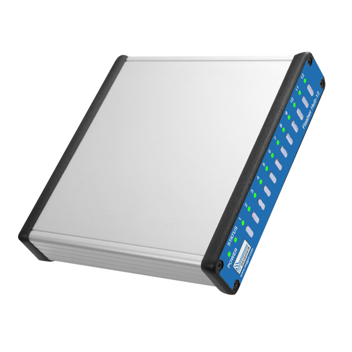
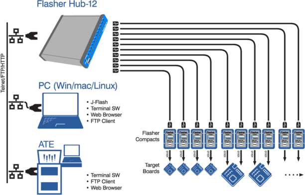
SEGGER’s Flasher Hub-12 controls up to 12 Flasher Compact units serving as individual channels for parallel, high-speed gang programming. Each channel can be configured to program a different device or a different firmware image.
The Flasher Hub-12 is set up just once per channel using SEGGER's Flasher software package. The software depends on the type of flash chip being programmed. The Hub can receive commands and send results "stand-alone" via TELNET, a desktop PC is not required for control.
The combination of a single Flasher Hub-12 and up to 12 Flasher Compacts is the perfect solution for high-volume multi-panel and multi-target mass production.
Supported devices
SEGGER Flashers support a wide range of CPU cores and an even wider range of different devices, such as SPI-Flash devices.
This includes support for tens of thousands of devices in hundreds of device families with billions of devices programmed.
Universal target support
The Flasher Hub supports all flash devices and programming interfaces supported by the Flasher to which it is connected. By using Flasher Compact as modules, the Flasher Hub takes advantage of the extensive list of supported devices and target interfaces, plus the ultra-fast programming speed and reliability, of these almost-anything-programmers.
Software
All software is included free of charge. It comes with the flash loaders for all supported devices.
Updates
Future software and firmware updates as well as any new flash loaders for target devices that will be added, are also free of charge.
- No licensing costs, even for newly added devices.
- No hidden costs.
- No future costs.
Multi-platform
As a multi-platform solution, Flasher Hub comes with the application software for Linux, macOS and Windows. Software and firmware updates are included. Similarly, use on all currently supported target devices, and any that will be added, is also included.
Parallel programming
The Flasher Hub controls multiple Flasher Compacts. A single Flasher Hub-12 supports up to 12 Flasher Compacts, and up to 4 Flasher Hub-12 devices can be chained, enabling the administration and control of up to 48 programming channels. Each Flasher can be configured individually to program different targets with different target firmware simultaneously.
Whether it’s the number of channels, type of flash device, firmware image, programming interface or command interface, the Flasher Hub can manage them all.
 Flexible control and monitoring
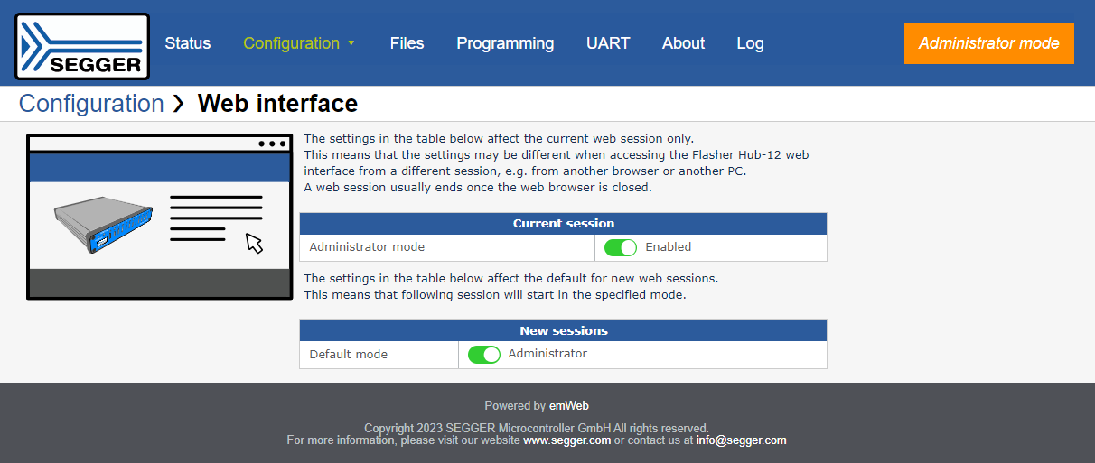
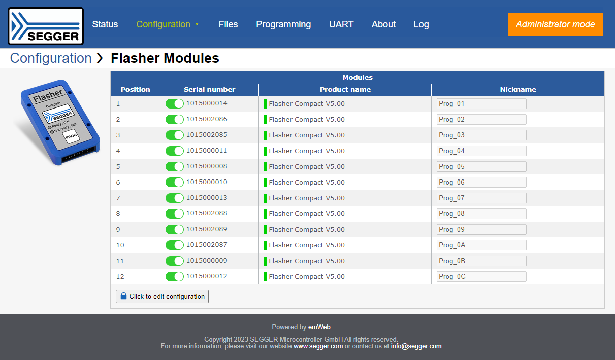
The Flasher Hub is easy to set up using SEGGER software tools. It can be operated via TELNET using the built-in ASCII command interface which was designed for automation. Flasher Hub also comes with a web interface designed for easy and intuitive manual operation.
Serial number assignment
Many modern devices require some pieces of unique information.
The Flasher Hub allows the programming of data that differs amongst other otherwise identical units. Typical examples are things like serial numbers, ethernet hardware addresses (MAC), and digital signatures, and license keys that enable/disable product features. All these options can be adapted from device to device by applying patch data to the original firmware while programming.
Built-in web server
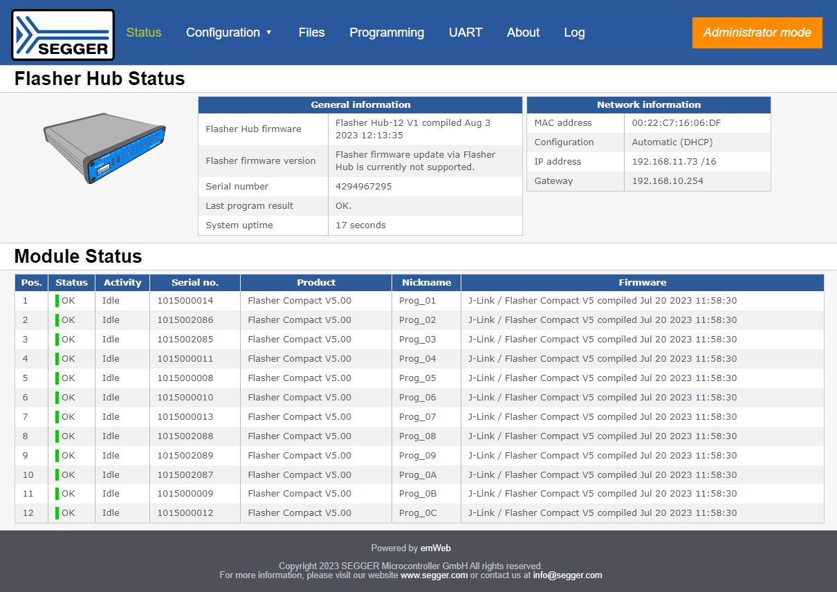
The built-in web server of the Flasher Hub (using emWeb) simplifies configuration and setup of the programming system. In addition it offers options to check status information remotely and to manage firmware images.
Remote monitoring
The built-in web server is designed to present important device and current operation data for a quick overview and, additionally,to check the status of the programmer, providing information about:
- Installed firmware version
- Hardware version
- Power consumption
- IP configuration
- Network load
- Current operation and status
- Programming interface in use
This may be important for fast troubleshooting through code verification, for instance, as it is when executing a cyclic redundancy check (CRC) that helps to detect errors during data transmission or storage.
Configuration
If needed, the built-in web server programmer settings can be checked and adjusted. These could, for example, be parameters like:
- Subnet mask
- Gateway
File management
The built-in web server enables file management for all connected modules. This includes
- Firmware images
- Setup files
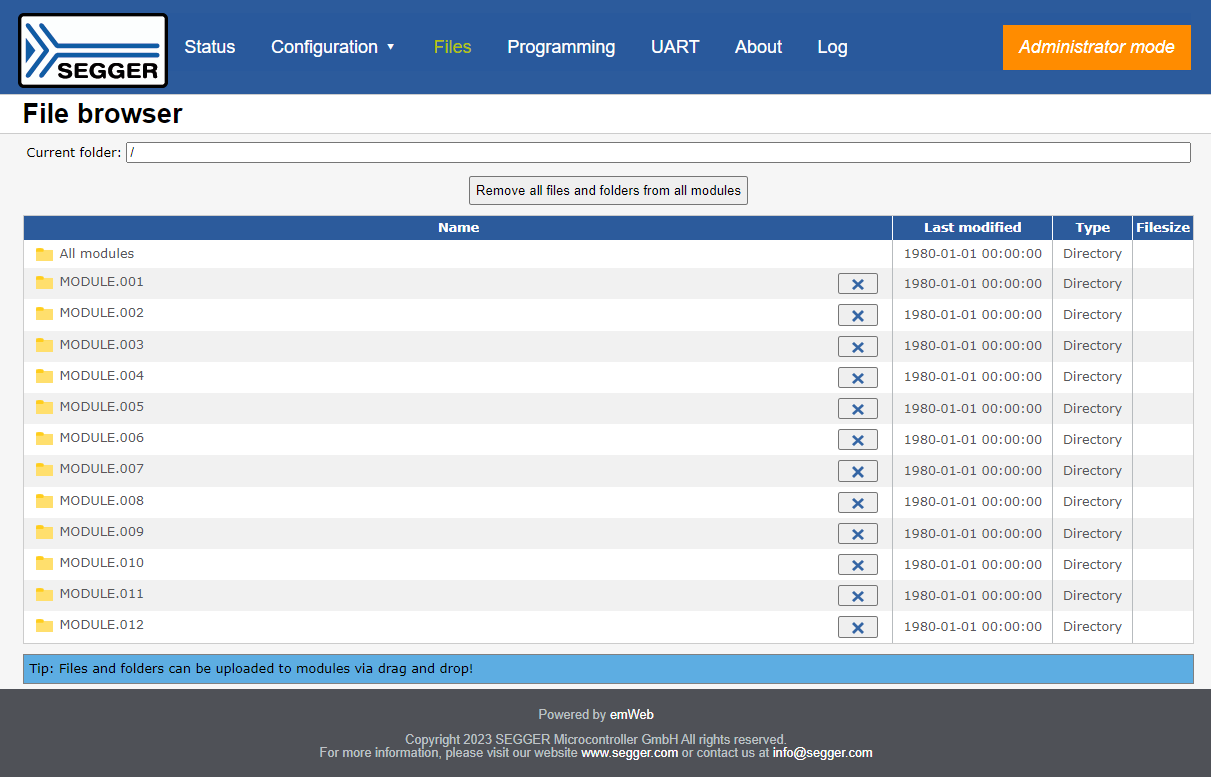
Built-in FTP server
The Flasher Hub also includes the built-in FTP server, to upload firmware and configuration or download log files.
Remote file update
Using the emFTP server enables easy upload of configuration files and firmware images. By connecting to the emFTP server using an FTP client of choice, files can be transferred between client and Flasher.
Having access to the Flasher configuration via FTP enables configuration of multiple Flashers from a central production control server. This interface also can be used to make the production line part of a CI/CD system to push stable releases into the current production.

Log file
Analyzing the reliability of the production line is an important task, when it comes to increasing the production frequency. This purpose is supported by the built-in FTP server, which lets users check the history of past programming cycles via log file download. Each entry provides the following information:
- Result (success/failure)
- Duration
- Serial number (if programmed)
For failed programming cycles, the log file provides additional information for quick troubleshooting (e.g. failed to open Flasher config file).
Use case
In-system programming for complex manufacturing lines
In addition to supporting programming unique serial numbers and patch data. It also allows updating and monitoring from a nearby production control office. This means the programming process is closely connected to testing facilities, such as ATE (Automatic Test Equipment) and similar devices. In practice, this means:
- Fast & easy data transfer from development to production
- Easy monitoring & updating from a nearby location
In-system programming processes in mass production also come with a ready-to-use communication channel and TELNET interface. These can be used to control its operation. Additionally, built-in web/FTP servers allow updates and monitoring.
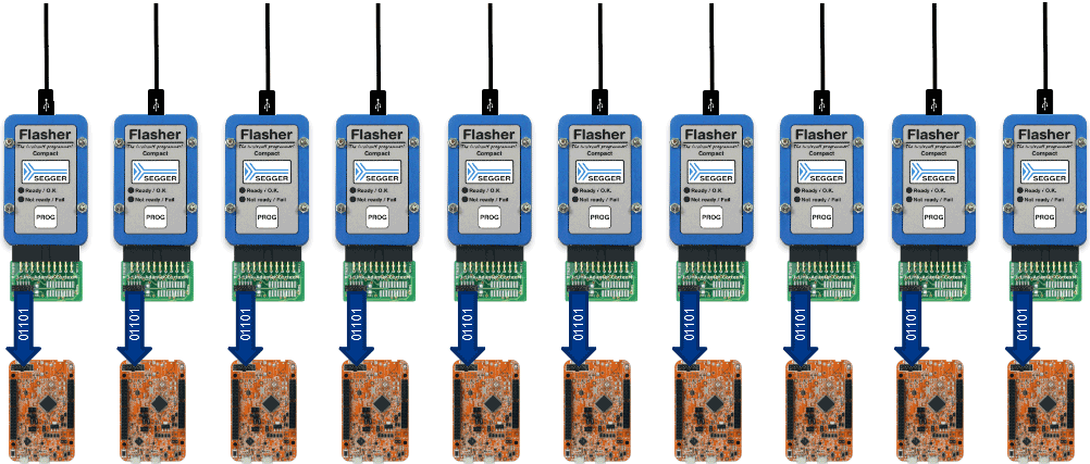
Flasher Compact units connected to target boards
| Specifications | |
|---|---|
| Power supply | 8-30 VDC, reverse polarity protected, max. 60 W[1] |
| Power comsumption | Max. 15 W |
| USB Flasher interface | USB-C 2.0 |
| Host interfaces | USB Type-B (Upstream), USB Type-A (Downstream), Ethernet, RS232 9-pin |
| Operating temperature | + 5 °C ... + 60 °C |
| Storage temperature | - 20 °C ... + 65 °C |
| Relative humidity (non-condensing) | < 90 % rH |
| Size (without cables) | 170 mm x 172 mm x 35 mm |
| Weight (without cables) | 660 g |
[1] Depends on current consumption of connected downstream devices. For maximum load the input supply must provide 12 VDC or more.
Tecnologix offre supporto gestito direttamente dal Team di sviluppo.
Non esitare a metterti in contatto con i nostri esperti.
Basta chiedere qui