We use cookies to make your experience better. To comply with the new e-Privacy directive, we need to ask for your consent to set the cookies. Learn more.


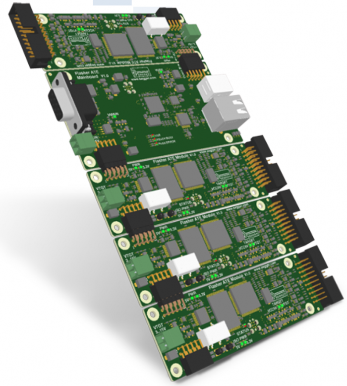
Flasher ATE is perfectly suited for high volume mass production environments. The modular system uses a communication main board at its heart, that distributes the commands received from an ATE, ICT or a similar automated production handler system to the programming modules. Each programming module can be set up with individual configurations and firmware. The Gang Programmer is capable to program multiple devices in parallel, whether these devices are equal or part of a multi-device system, Flasher ATE can handle all production setups.
The Gang Programmer Flasher ATE is an in-circuit-programmer for high volume mass production. To accommodate for the special requirements in high volume production environments, the Gang Programmer can be mounted in 19” racks or be connected directly to an ATE. The interfaces to start and monitor the programming tasks have been designed with the implementer of the production system in mind. The number of target interfaces per mainboard can be scaled up to 10 programmer boards. The ultra fast target interface technology has proven its reliability in the market-leading family of J-Link debug probes and Flasher programming devices.

DEVICE UNDER TEST (DUT) SUPPORT
Production environments require more than just creating and programming. Once the production cycle is started, there are all kinds of verifications taking place. The target interfaces of the Flasher ATE Gang Programmer modules include a UART transceiver. This UART transceiver can be managed from the ATE or similar production handler devices via the connection with the Flasher ATE base board. Once it is activated, serial communication via pin 5 and pin 17 is mapped to an IP connection, so the ATE is able to communicate with the freshly programmed device without requiring additional hardware.
 Support")
GETTING STARTED
The Flasher ATE can be used for programming flash targets stand-alone. It has to be prepared by using either the J-Flash Software or the Universal Flash Loader Configurator.
SETTING UP FLASHER ATE FOR THE FIRST USE
In order to use Flasher ATE for the first time, you need to install the Flasher ATE related software and documentation pack which, among others, includes the J-Flash software. Then, connect the Flasher ATE to the network via ethernet. The Flasher ATE is preconfigured to obtain an IP address via DHCP or autoconfiguration.
Download J-Link Software and Documentation Pack for Windows
Download Flasher ATE Getting Started (AN08007)
Download Flasher ATE User Manual (UM08035)
Power-on sequence
In general, the Flasher ATE should be powered on before connecting it to the target device. That means you should first connect the Flasher ATE to the host system via USB or an external power supply and then connect the Flasher ATE to the target device via JTAG.
USING FLASHER WITH PC SOFTWARE "J-FLASH"
J-Flash is a software running on Windows (Windows 2000 or later) systems and enables you to program your flash EEPROM devices via the JTAG connector on your target system. J-Flash works with any device/core that is supported by J-Link and supports all common external flashes, as well as the programming of internal flash of ARM microcontrollers. In order to use J-Flash with the Flasher ATE, the configuration and data files, generated by J-Flash, have to be manually uploaded to each Flasher ATE module via the integrated FTP server.

LED STATUS INDICATORS
Progress and result of an operation is indicated by Flasher ATE Mainboard LEDs:
| Status of LED | Meaning |
|---|---|
| USB GREEN | USB connection established or no USB present. |
| USB RED | Bootloader active. |
| READY/BUSY GREEN | Idle. |
| READY/BUSY RED | Programming (>= 1 module). |
| PASS/ERROR GREEN | Programming operation successful (all modules). |
| PASS/ERROR RED | Programming operation failed (>= 1 module). |
PROGRESS AND RESULT OF AN OPERATION IS INDICATED BY FLASHER ATE MODULE LED:
| Status of LED | Meaning |
|---|---|
| GREEN, slow blinking (~1 Hz) | Programming. |
| RED | a) The module is in bootloader mode. b) The last operation has failed. |
REMOTE CONTROL OF THE FLASHER ATE
The Flasher ATE can be remote controlled by automated test equipment without the need of a connection to a PC. Therefore the Gang Programmer is equipped with additional hardware control functions, which are connected to the SUBD9 male connector, normally used as a RS232 interface to PC. The adjacend diagrams show the internal remote control circuitry of Flasher. As the remote control circuit only allows limited control of the flash process (trigger all modules at once), the preferred method to control the Flasher ATE is either the RS232 interface or a telnet shell via ethernet. This command line interface allows a detailed control of the flash process of each module as well as putting each module into the UART transceiver mode mentioned above.


| Pin | Function | Description |
|---|---|---|
| 1 | START | A positive pulse of any voltage between 5V and 30V with duration of min. 30 ms starts the "Auto" function on all modules (typically erase / program / verify) on falling edge of pulse. The actions to perform can be configured in J-Flash. |
| 4 | BUSY | As soon as "Auto" is started, BUSY becomes active, which means that transistor is switched OFF. |
| 5 | GND | Common Signal ground. |
| 7 | OK | This output reflects result of last action. It is valid after BUSY turned back to passive state. The output transistor is switched ON to reflect OK state. The last action is considered to be successful, only if all modules report back successful programming. |
SOFTWARE CONTROLLED OPERATION
If you need full control of the operations of the Flasher ATE you can use the Telnet or RS232 interface for sending commands and receiving qualified result statements.
In contrast to the hardware handshake protocol you can trigger every action of the Flasher ATE separately. Also the commands can be executed individually for every module.
CONFIGURING FLASHER ATE VIA FTP
The Flasher ATE includes an FTP server for easy upload of the configuration files. The Flasher ATE provides a virtual sub folder for very connected flash module. Just upload your configuration and data file, created with the J-Flash tool or Universal Flash Loader Configurator tool, with any FTP client tool into the modules sub folder.
Once you have selected your project file with the "select" command or edited the flasher.ini file in the sub folder of the module, the Flasher ATE is ready for use.
SUPPORTED DEVICES
The Flasher ATE supports a wide range of CPU cores and an even wider range of different devices from various vendors. On this page, an overview of all supported CPU cores as well as devices for which flash programming is supported, is given.
SUPPORTED CPU CORES
The following CPU cores are currently supported by the Flasher ATE:
|
|
|
LIST OF SUPPORTED DEVICES FOR FLASH PROGRAMMING
The following list gives an overview about which devices are known by the Flasher ATE and are available for flash programming. In case of doubt or if you want to request additional device support, please feel free to get in touch with SEGGER: info@segger.com.
The list below is always valid for the latest version (highest version number) of the J-Link/Flasher software package. This may be a release (even version number) or beta version (odd version number), since support for some devices is usually added in a beta phase first.
UNIVERSAL FLASH LOADER
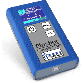
Besides programming the flash memory via the debug interface (JTAG), there are some devices which are programmed via a device-specific programming interface. These interfaces can be supported by the Universal Flash Loader, a feature for the Flasher ATE, Flasher PRO and the Flasher Portable PLUS. The Universal Flash Loader supports the serial programming interface of the Renesas RL78 device family, based on a 16 bit microcontroller including over 1000 devices.
UNIVERSAL FLASH LOADER CONFIGURATOR
The Universal Flash Loader Configurator is a software utility to prepare the Flasher for programming. It includes a device database and a comfortable user interface for configuration. The configuration and data files can be directly downloaded via USB to a connected Flasher ATE, Flasher PRO or Flasher Portable PLUS. The utility is able to save the configuration settings into a project file for later use, so the image file can easily be upgraded. The Universal Flash Loader Configurator is available for download here.
MANUAL SETUP
Besides using the Universal Flash Loader Configurator, it is also possible to manually create or edit a configuration. This might be of interest for very new devices which are not yet known to the configuration utility. The configuration files for the Universal Flash Loader are in the human readable ini file format. For a detailed description of the individual properties please refer to the Flasher ATE User Guide (UM08035).
LIST OF SUPPORTED DEVICES FOR FLASH PROGRAMMING
The following list gives an overview about which devices are available for flash programming using the Universal Flash Loader. In case of doubt, please feel free to get in touch with SEGGER: info@segger.com.
The list below is always valid for the latest version (highest version number) of the J-Link/Flasher software package. This may be a release (even version number) or beta version (odd version number), since support for some devices is usually added in a beta phase first.
| Power Supply | USB powered or via external power supply (5V). Max. 3A using 10 modules. | ||||
|---|---|---|---|---|---|
| Ethernet Host Interface | 100/10 MBit | ||||
| USB Host Interface | USB 2.0 | ||||
| RS232 Host Interface | RS232 9-pin | ||||
| Target Interface | JTAG 20-pin (14-pin adapter available) | ||||
| Max. target cable length | Recommended (delivered): 20cm (8") Max. 2m (6.5") allowed but might reduce max. target interface speed. | ||||
| Serial Transfer Rate between Flasher PRO and Target | Max. target interface (JTAG, ...) speed: 15MHz | ||||
| Supported Target Voltage | 1.2 - 5V | ||||
| Current drawn from target voltage sense pin (VTRef) | < 25µA | ||||
| Target supply voltage | 3 - 15V (5V with no additional supply.) | ||||
| Target supply current | Max. 400mA (100mA with no additional supply.) | ||||
| Operating Temperature | + 5 °C ... + 60 °C | ||||
| Storage Temperature | - 20 °C ... + 65 °C | ||||
| Relative Humidity (non-condensing) | < 90% rH | ||||
| Size (without cables) | Mainboard: 108mm x 56mm x 20mm Module: 108mm x 35mm x 20mm | ||||
| Weight (without cables) | Mainboard: 47g Module: 24g | ||||
| Supported OS | Microsoft Windows 2000 Microsoft Windows XP Microsoft Windows XP x64 Microsoft Windows 2003 Microsoft Windows 2003 x64 Microsoft Windows Vista Microsoft Windows Vista x64 Microsoft Windows 7 Microsoft Windows 7 x64 Microsoft Windows 8 Microsoft Windows 8 x64 Microsoft Windows 10 Microsoft Windows 10 x64 | ||||
- In-System Programmer (ISP)
- Ultra fast programming
- Control interfaces for ATEs and similar production process handlers
- Switchable target power
- J-Flash for an easy setup
- Scalable solution with up to 10 individual channels
- Parallel channels, no demultiplexing required
- Galvanic isolation of each module
- Target supply voltage may be up to 15V
- Gang Programming
Tecnologix offers support which is directly handled by development team. Do not hesitate to get in touch with our experts.
Just ask here
We found other products you might like!